

产品描述
Technical characteristics
☆ Drive voltage: 10V~40V DC power supply.
☆ H-bridge bipolar constant phase current drive.
☆ Eight output currents of 3A can be selected.
☆ Seven subdivision modes of 64 subdivision are optional.
☆ Input signal photoelectric isolation.
☆ Standard cation monopulse interface.
☆ Offline holding function.
☆ Semi closed enclosure can adapt to more severe environment.
☆ Provide energy-saving automatic half current locking function.
Electrical characteristics (at ambient temperature Tj = 25 ℃)
Power supply | 10V~40VDC,capacity0.03KVA |
Output current | Peak 3A/phase (Max) (output current can be set by panel dial switch) |
Drive mode | Constant phase current PWM control |
Excitation mode | Whole step, half step and 4, 8, 16, 32 and 64 subdivision methods |
insulation resistance | > 100M Ω under normal temperature and pressure |
Insulation strength | 0.5KV under normal temperature and pressure for 1 minute |
Operating environment and parameters
Cooling mode | 自然冷气(恶劣情况下需外加辅助散热) | |
Operating environment | Occasion | 尽量避免粉尘、油雾及腐蚀性气体 |
temperature | 0℃~+50℃ | |
humidity | < 80% RH, no condensation, no frost | |
vibration | 5.9m/s2Max | |
保存温度 | -20℃~+65℃ | |
外形尺寸 | 116×60×37mm | |
重量 | 0.21Kg | |
Supply voltage
The switching power supply design inside the driver ensures that it can adapt to a wide voltage range. Users can choose between 10V and 40VDC according to their own conditions. Generally speaking, higher rated power supply voltage is conducive to improving the high-speed torque of the motor, but it will increase the loss and temperature rise of the driver.
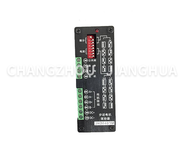
Output current selection
The output current value of the driver is 3A/phase (peak value). Eight states can be combined through the fifth, sixth and seventh digits of the six digit dial switch on the driver panel, corresponding to eight output currents, ranging from 0.9A to 3A (see the current selection table for details), for use with different motors.
Note: The white square on the panel screen corresponds to the actual position of the switch.
five
six
seven
five
six
seven
five
six
seven
five
six
seven
seven
ON
ON
ON
0.9A
ON
OFF
ON
1.5A
ON
ON
OFF
1.2A
ON
OFF
OFF
1.8A
OFF
ON
ON
2.1A
OFF
OFF
ON
2.7A
OFF
ON
OFF
2.4A
OFF
OFF
OFF
3A
Subdivision Selection
The driver can provide seven operation modes: whole step, half step improvement, 4 subdivision, 8 subdivision, 16 subdivision, 32 subdivision and 64 subdivision. Different states can be combined by using the first, second and third digits of the six digit dial switch on the driver panel (see the subdivision mode selection table for details).
Note: The white square on the panel screen corresponds to the actual bit value of the switch.
1 | 2 | 3 | 1 | 2 | 3 | 1 | 2 | 3 | 1 | 2 | 3 | ||||
ON | ON | ON | retain | ON | OFF | ON | 32to subdivide | ON | ON | OFF | 8to subdivide | ON | OFF | OFF | half of step |
OFF | ON | ON | 64to subdivide | OFF | OFF | ON | 16to subdivide | OFF | ON | OFF | 4to subdivide | OFF | OFF | OFF | Whole step |
Automatic half current
If the upper control computer does not send a step pulse signal within half a second, the driver will automatically enter the power saving half current operation mode, and the phase current of the motor winding will be reduced to half of the set value. In this state, the power consumption of the motor and the driver will be reduced, but the output torque of the motor will also be reduced accordingly. The driver automatically recovers the output current to the rated value when the next pulse arrives.
Phase staggering protection
When the two-phase motor is connected with the driver, the user is easy to connect the wrong phase, thus seriously damaging the driver. The driver has designed a phase error protection circuit. The driver will not be damaged even if the user is connected to the wrong phase, but the motor will operate abnormally, which is mainly reflected in the small output. In this case, check whether the motor wiring is correct.
About heat dissipation
High operating temperature is the root cause of most circuit faults, and effective heat dissipation is particularly important for improving reliability and operating life. It is recommended to tightly fix the drive on the user's metal chassis to assist in heat dissipation through the chassis backplane. If conditions permit, heat conducting materials such as silicone grease can also be added to the contact surface. If a cooling fan is added, the temperature rise of the drive will be greatly reduced.
Input signal
The connection terminal of the driver is a pluggable terminal, which can be unplugged first and then plugged in after wiring. Note: In order to avoid accidental loss of the screws on the terminal, the screws on the terminal should also be tightened when there is no wiring.
Common terminal: the input signal of the driver adopts common anode wiring mode. The user should connect the power supply positive pole of the input signal to the terminal, and connect the input control signal to the corresponding signal terminal. The low level of the control signal is valid. At this time, the corresponding internal optocoupler is connected and the control signal is input into the driver.
Pulse signal input: when the anode is common, the falling edge of the pulse signal is interpreted as an effective pulse by the driver and drives the motor to run for one step. To ensure the reliable response of pulse signal, the duration of pulse low level shall not be less than 10 μ s。 The signal response frequency of this driver is 70KHz. If the input frequency is too high, the correct response may not be obtained.
Direction signal input: the high level and low level of the signal at this end control the two turns of the motor. When the anode is common, this end is suspended, which is equivalent to the input high level. When controlling the motor rotation, ensure that the direction signal pulse signal is at least 10 μ S, which can avoid the wrong response of the driver to the pulse.
Offline signal input: this end receives the high/low level signal output by the control machine. When the anode is shared, the motor phase current is cut off at the low level, and the rotor is in the free state (offline state). The rotor is locked when the anode is high or suspended.
Typical Connection Diagram
| be careful: In order to better use the driver, the user should follow the principle of separating the power line (motor phase line, power line) from the weak current signal line when connecting the system to avoid the interference of the control signal. Use shielded cables to transmit control signals when it is impossible to wire separately or there are strong interference sources (frequency converter, solenoid valve, etc.); It is also significant to use higher level control signals to resist interference. |

Outline dimension drawing
(Unit: mm)